Layout of Components Diagram broken when adding inner components

0 votes
asked Mar 20, 2022 in Bug by bfxdev (120 points)

Hello,

this is my first message on this forum. I want to describe a software system composed of many processes, thread pools, queues, databases etc distributed over several computers.

So the plan is to have a large, highly-detailed diagram, on which I can remove some inner components depending on the focus (e.g. with "!if" or "remove" tags).

But layout issues appear when I try to make components appear inside other components. My naive definition:


@startuml
component "My system without details" {
  component Client{
  }
  component Server {
  }
  Client -r- Server
}
component "My system with details" {
  component Detailed_Client {
    [Application]
  }
  component Detailed_Server {
    [Service]
  }
  Detailed_Client -r- Detailed_Server
}
@enduml


Leads to:

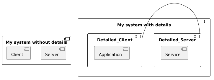
As you can see, just adding the inner components Client and Server breaks the layout. The link between the client and the server would be [hidden] in my real diagram, here displayed just for explanation.

I already spent a lot of time trying to tweak, including:

  • Left to right direction: not a real solution, at the end my diagram will have parts that are better with letf-to-right or top-to-bottom, so I want to keep the default direction where at least "r" really means "right"
  • [norank] on the link Client/Server: still unclear to me what it does
  • ranksep/nodesep: just the spacing between components in vertical/horizontal directions
  • Changing the directions of the arrows, changing the order of components: somehow changing the result, but still unpredictable

Actually, the only thing that worked so far is to:

  • remove the client-server link
  • re-order, first server then client

Now I'm a bit worried for the rest. I fear that adding more complexity in my diagram will lead to more jumps in the layout, i.e. I need to concentrate more on layout workarounds than on the content.

Any Idea?

2 Answers

0 votes
answered Mar 20, 2022 by The-Lu (63,920 points)

Hello B.,

See also some other questions/answers on this forum on the same topic...

Then, a possible workaround is ti use `left to right direction`, as :

@startuml
left to right direction 

component "My system with details" {
  component Detailed_Client {
    [Application]
  }
  component Detailed_Server {
    [Service]
  }
  Detailed_Client -- Detailed_Server
}

component "My system without details" {
  component Client{
  }
  component Server {
  }
  Client -- Server
}
@enduml


If that can help,
Regards.

commented Mar 20, 2022 by bfxdev (120 points)

Hello and thanks for the very prompt answer.

As I wrote in my first message, after looking at many workarounds, I know that "left to right direction" would more or less work, but it is no really acceptable solution.

First, just a bit annoying, you have to swap all right/left and up/down (why should the user have to do that? "right" should remain "right")

Second, the workaround works with this example but obviously it is no general solution. If I continue to add components up and down, then the same problem appears again:


@startuml
left to right direction 

component "My system with details" {
  component Detailed_Client {
    [Application]
  }
  component Detailed_Server {
    [Service]
  }
  component Detailed_Database {
    [Data Lake]
  }
  component Detailed_Controller {
    [Start]
  }
  Detailed_Client -- Detailed_Server
  Detailed_Server -l- Detailed_Database
  Detailed_Server -r- Detailed_Controller
}

component "My system without details" {
  [Client]
  [Server]
  [Database]
  [Controller]
  Client -- Server
  Server -l- Database
  Server -r- Controller
}

@enduml

It results in:

Any known workaround for this case?

Again thanks for your help in any case.

0 votes
answered Mar 20, 2022 by Martin (8,360 points)
edited Mar 20, 2022 by Martin

The problem is Container shapes and the way Plantuml draws them using Graphviz.  Plantuml (entirely sensibly) represents containers as 'clusters' in Graphviz.  However, Graphviz has a huge short-coming - it does not support linking to/from clusters.  It only supports connecting to a shape contained within a cluster and truncating the arrow to/from that shape at the container's boundary.  This forces Plantuml to place a 'point' shape inside the cluster and use it for connections representing the container.  But this point shape will end up on the left-hand side of the container and Graphviz's line-crossing reduction kicks in and draws unhelpful arrow paths and trying to control the direction doesn't work.  See here for what I'm trying to describe (imagine the red arrow clipping at the outer red boundary).  The-Lu's "left to right" answer works because the points become placed at the bottom of the clusters rather than at the left-hand-side like this.

Your simple example lends itself to subdiagrams.  Putting a subdiagram inside a shape is like putting a picture inside - it doesn't turn the shape into a container.  The downside is that the subdiagram has to be self-contained, which might be too big a constraint for you because it wouldn't scale to a third level of detail.  But here is what I mean (click diagram for source):


(Eventually "!pragma layout smetana" might work - it is designed to avoid using Graphviz and hence the limitations of Graphviz.  But at present it doesn't seem to support links between containers either.  There's supposed to be yet another layout engine called "elk", but that crashes on this diagram!  So the alternative layout engines don't work here.)

commented Mar 21, 2022 by bfxdev (120 points)

Thanks for the detailed answer.

I tried as well to use a sub diagram, which is a very promising general feature that reminds me of what you can do with e.g. MagicDraw/Cameo. But it has several drawbacks, the last one is a no-go for my large system map project:

  • I could not find documentation. In the official PDF it is only mentioned rapidly in the section 14.15 Include Salt on activity diagram. It could be described more generally in section 8.
  • The border color of the sub-diagram is not the same as the enclosing block. It is surely manageable by a specific theme. BTW the color of a component changes as soon as it contains other elements, what is the skinparam of this color? 
  • Sometimes the font size is a bit different in sub-diagrams
  • Finally, I see no way to connect inner elements of different sub-diagrams, which is the ultimate goal of the exercise. In my opinion it is completely OK that sub-diagrams cannot be connected together, as a sub-diagram should only be a context-less reminder of another diagram (should not become a feature request).

Meanwhile I started to look at the code generated for Graphviz. And yes I discovered the "clusters" and the extra point added to the diagram. For the records, this question on StackOverflow shows how to connect sub-graphs. Using ltail/lhead is not necessary in the code generated by PlantUML because several layers of clusters are generated, and the invisible point is already at a surrounding invisible cluster layer.

BTW, there are many extra layers added by PlantUML. This is probably to try to constrain GraphViz, but at the end the extra clustering leads to inconsistent spacing between Components in the diagram. There is apparently no way to control this spacing from PantUML (linked to the "margin" setting of GraphViz, not to nodesep/ranksep).

Actually PlantUML could have a different strategy than creating the invisible point "zacl", which gets placed by GraphViz almost randomly.

In case we have inner elements in a component (or any other block), another strategy would be to point to one of the inner elements (let's say the first one in general), It would look like this:

But well, I can imagine that other corner cases would arise. I bet I will wait for a complete implementation of "smetana" for a better result (or get involved). How far it is?

Meanwhile I'm creating my diagram in the "left-to-right" fashion only, which makes a veery long horizontal diagram, so far without layout jumps.

In any case thanks for the support.

commented Mar 21, 2022 by Martin (8,360 points)

Graphviz is the reason for Plantuml's initial success and fast growth, but it has started to rather hold it back.

The border color of the sub-diagram is not the same as the enclosing block. It is surely manageable by a specific theme. BTW the color of a component changes as soon as it contains other elements, what is the skinparam of this color? 

Adding "skinparam backgroundcolor transparent" to the subdiagrams should eliminate the border color issue.
I bet I will wait for a complete implementation of "smetana" for a better result (or get involved). How far it is?
I may have projected my own hopes onto Smetana...its stated goal is to rewrite Graphviz in java so that Plantuml is more portable.  I have no idea whether the team would have the appetite (or skills - I mean I assume Graphviz has avoided properly integrating clusters for a reason) to then morph the implementation into a better fit for Plantuml.

In case we have inner elements in a component (or any other block), another strategy would be to point to one of the inner elements 

I agree.  I think this would work better than using the point shape - I'll raise a wanted feature and see what they say.  It's not perfect, because Graphviz doesn't layout each cluster with respect to the global graph - see diagram below - but that's nothing that a hidden dependency couldn't cure.


commented Mar 22, 2022 by Martin (8,360 points)

I had a go at raising a Wanted Feature for this idea - please feel free to add ideas/comments to it.

...